
By Carl W8WZ
NOTE: This article originally appeared in the Raleigh Amateur Radio Society’s October 2020 Exciter newsletter.
It all started because Field Day was cancelled. Due to the Corona virus and social distancing protocols the Raleigh Amateur Radio Society had to cancel our annual group Field Day effort in 2020. Instead, RARS encouraged each member to operate during Field Day from his or her own home.
That led me to think about how I would operate. I decided it would be a good time to test out and use my new generator. Then I decided that instead of just operating from my shack I might like to spend some time operating from the back porch. Then I decided it might be nice to regularly operate from the back porch. That meant that I needed an antenna that I could use from the back porch.
The two HF antennas I had at the time were both inverted Vees fed with ladder line. One is cut for 80 meters and fed with open wire 600ohm feeders and is up 100 feet at its apex. The other is a total of 100 feet long and center fed with commercial 450ohm window line. That antenna is up at an apex of about 70 feet. Neither one could be easily accessed from the back porch because getting the feedlines into the station took a good bit of work and I did not want to mess with them now that they were set up.
This meant that the solution would be a third antenna. My city lot is small but it abuts a woods and I have a few 100 feet tall trees (oaks and pines) in the back of my yard that make great antenna hangers. But since I already have two full size HF antennas in the yard, I was limited for third antenna options. I do not have any deed covenant restrictions or restrictive zoning. However, I am particular about the appearance of my yard and did not want an antenna that would particularly draw attention to itself.
I first considered a vertical that could fit in an open space behind my shed. I have used verticals in the past and found them to be fine antennas. However, I decided against that option in this case because for Field Day (and other nets I participate in on 80 meters) I wanted my 80-meter ground wave signal to be horizontally polarized as much as possible because verticals don’t do a great job of allowing us to work nearby stations on 80 meters and I wanted to do that for Field Day and nets. That is when I began to look at the end fed antennas that have gained popularity in recent years. I talked with several friends who use them and read several different articles about them. My fellow QCWA Piedmont Chapter 126 weekly 75-meter net participants were very helpful in sharing their experiences. I had never really been that excited about them in the past. In college I end fed a random wire that I threw out the window into some trees and used the dorm room radiator as ground. That resulted in some fun contacts and also in a lot of RF in the “shack”. I also questioned the efficiency and power handling abilities of the torrid matching systems I saw being used in these new antennas. But, I thought this might be a good opportunity to try something new.
So I decided to go that route. I looked at several different end fed antenna options. Some require the use of a long coax feedline. I decided against those options thinking that meant that they don’t really have a good match at their feed point and are using a section of lossy coax to hide that bad match from the SWR meter at the transmitter or they are prone to excessive common mode current issues and using long coax to try and minimize that problem. I also stayed away from designs that said coax feed line length had to be a certain length based on wavelength. That made me think that they were using the feedline as part of the antenna system’s matching process and that it would also radiate. I didn’t want that. Some designs said that a tuner will be needed. I do not like using coax at high SWR under any circumstances. Even the best coax has unacceptable loss when SWR is high. For high SWR situations I only use ladder line. So I discarded any antenna that said a tuner would be needed. I also wanted an antenna that could handle legal limit power. Even though I would not be using more than 100 Watts for Field Day, I wanted the option to use my amplifier with the antenna in the future.
Considering these criteria led me to the EFHW-8010 made by Myantennas.com. I ordered the antenna from their webpage and within a few days it was in my mailbox and ready for installation. The antenna appeared very well built and it was well packaged.
I considered the different ways this antenna can be mounted and I decided on an Inverted-L configuration. My thinking for this was based on the fact that I have tall vertical supports nearby and it is easier for me to go up than across on my property and that if I went horizontal at less than ½ of a wavelength my radiation angle would be unhelpfully high. While I want to make good local contacts on 80 meters, I did not want an NVIS system on any band higher than 80 meters. My plan was to go up 66 feet and then go horizontal for the remaining 66 feet. I wanted to run the horizon- tal section to the South so that my radiation lobes would go East/West. Since I live in North Caroli- na, an East/West pattern is nice as it covers both the rest of the United States as well as Europe. I thought this system should give me both vertical and horizontal radiation and the horizontal radiator will be adequately high for all bands except 80.
There was a 4”x4” fence post in my back yard in exactly the right spot behind the shed. So I drove an 8-foot ground rod into the ground at its base and mounted the antenna’s matching section to that fence post. I then grounded it to the ground rod. My friends Al (N4EII) and Mark (KM4JRH) came over with two potato guns, a bow and arrow, a sling shot, yards and yards of paracord and lots of fishing line. The installation began. The first shot was over an oak tree limb above the antenna to support the vertical portion of the inverted-L. We thought it to be about 60 to 65 feet up. Al made the shot perfectly on the first try with his compressed air powered launcher. Once we got the wire into the tree we realized it was actually 80 feet up. We decided that was fine. Mark then went into the woods and found a tree at the correct height and distance to our South to support the horizontal section of the antenna. Al again made a perfect shot with his launcher.
We discovered that it was best to attach 50lb test fishing line to the lightweight fishing line that his launcher used and then reel in the light weight line so that the 50lb test was over the tree. Then we could connect the Dacron paracord to the 50lb line and haul it up. Then we could attach the antenna to the paracord and raise the antenna. We learned that lesson on another antenna project we did that had much more comical results than this one. Once the antenna was in the trees as we desired it, we tied it off leaving plenty of slack in the system for trees to sway in the wind. Because this antenna is tied off in a woods where other people have access, I decided against using a weighted counterweight to support it as that may draw the attention of curious people. Instead I tied it off rather high on a tree where it is not noticeable.
So the finished antenna is an inverted L with an 80-foot vertical section and 50-foot horizontal section. The horizontal section runs from the North to the South at a height of 80 feet. The feedpoint is about 42 inches above ground and the antenna is grounded according to the manufacturer’s instructions to a driven 8-foot ground rod just below the feed point. That ground rod is bonded to my house’s ground system via buried #6 solid copper wire. Next we hooked up the antenna analyzer. The antenna looked very good on the analyzer. Mark has a very nice Rig Expert analyzer that connects to his computer. We measured that antenna at the feed point and it looked very close to the way that the manufacturer’s webpage said it should look. SWR is less than 2:1 on all amateur bands 80-10 except on 30 Meters where it is around 3:1 and needs the use of the radio’s built in tuner and also on the area around 29 Mc which I do not use often. Then we put 100 feet of coax on the antenna and ran that to the back porch. The antenna looked the same there as it did at the feed point. I finally started to get excited about these end fed antennas.
The chart below is from the manufacturer’s webpage:
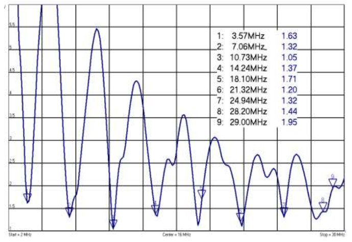
The data table below is as it is measured at W8WZ:
| Frequency | SWR from webpage | SWR Measured |
|---|---|---|
| 3.57 | 1.63 | 1.2 |
| 7.06 | 1.32 | 1.8 |
| 10.73 | 1.05 | Not a ham band |
| 10.1 | Not on webpage | 3.1 |
| 14.24 | 1.37 | 1:1 |
| 18.10 | 1.71 | 1.7 |
| 21.32 | 1.20 | 1.5 |
| 24.94 | 1.32 | 1.2 |
| 28.20 | 1.44 | 1.5 |
| 29.00 | 1.95 | 3.5 |
I will note that I can go as far into the phone band on 75 meters as 3.855 Mc before the SWR goes above 2:1. The company makes a different antenna that is designed for the 75-meter phone band. I chose the model that is designed for the 80 meter CW band as I operate there more often. On 40 Meters (the band I use most) the SWR is 1.8:1 on 7Mc. It is 1.7:1 on 7.028Mc (my fa- vorite frequency to rag chew on) and 1.3:1 up in the phone section.
After I knew that I could effectively couple RF into the wire I wanted to know how it actually performed. So the next day I patched together 200 feet of cheap RG58 Coax that I had laying around for use at Field Day or other portable set ups and brought the antenna feedline up into my radio shack. I put it on an A/B coax switch and compared it against the inverted Vee at 70 feet. It compared very favorably. Sometimes the End Fed was better and sometimes the Inverted Vee was better. There was no clear winner. The Inverted Vee often gave me higher signal strengths but a less desirable signal to noise ratio than the End Fed gave. Other times one was clearly better. I decided to call CQ on 40 CW on both antennas and see what numbers the Reverse Beacon Net- work system gave me. Here are the results of that initial test. As you can see, they matched my observation that there was no clear winner.
| RBN Station | EFHW | INV VEE |
|---|---|---|
| W1NT/6 | 14 | 37 |
| WE9V | 24 | 20 |
| K9TM-4 | 8 | 0 |
| KQ8M | 19 | 20 |
| K2DB | 13 | 0 |
Saying that the new antenna is at least equal to the old one was great news because my old antenna is a very solid performer. The new antenna has an advantage beyond its actual performance too, namely; ease of use. The Inverted Vee fed with ladder line requires me to adjust the tuner and sometimes the amplifier load control whenever I change frequencies. While this is not a hardship for most operations, it does slow me down in contests. I estimate that it costs me 1 to 2 QSOs every time I need to change bands based on my average QSO rate. It was also much easier to install than a dipole (even a dipole hung as an Inverted V. Also the ability to use coax as a feedline allows me to run the feedline in ways I cannot run the ladder line and to use a polyphaser for lightening protection with great ease.
So, I decided that I did not want to only be able to use this new antenna from the back porch. Instead I wanted to have access to it both on the porch and in the main shack. That meant finding the best coax feedline for this antenna. I wanted a feedline that was low loss, could handle full power, could be buried and would be UV resistant. I decided on the DX Engineering 400Max coax as the best way to meet those requirements. I also ordered a polyphaser lightening arrestor from DX Engineering at the same time.
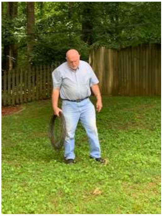
My friend Ken (AD4GX) came over with a gas powered edger and dug a trench from the antenna feed point across the back yard to the house. In that trench we buried the ground wire that bonded the antenna ground to the house ground and the direct burial coax.
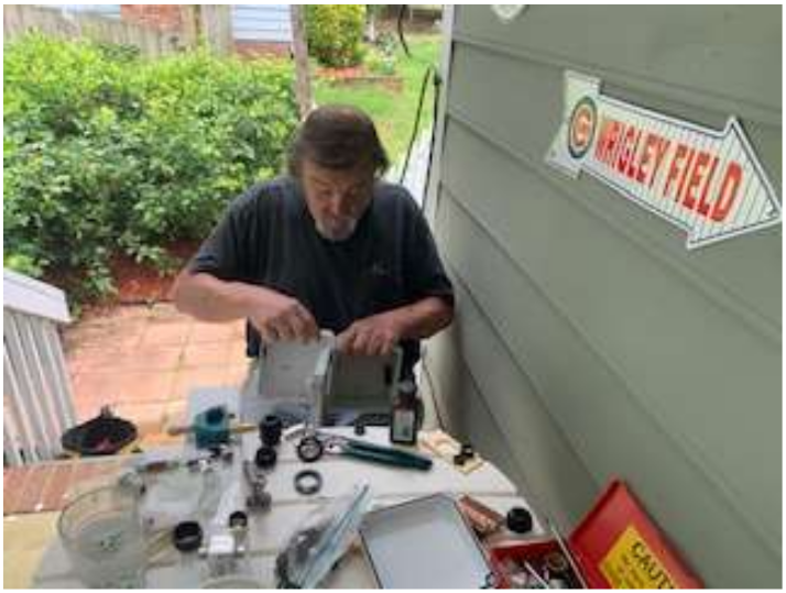
The coax comes out of the ground at the house where it connects to a polyphaser that is grounded at the house ground. Then another section of coax takes it to an A/B switch mounted (along with the polyphaser) on the side of the house inside of a water proof box that has a hinged door on it. 2-inch copper strap from Georgia copper connects the polyphaser to the ground rod. I can open the box, and switch between A and B. Side A allows me to connect a run of coax and sit on the back porch to operate. Side B connects to more DX Engineering 400 coax that is mounted to the side of the house and goes up into my radio shack.
To get the coax into the radio shack, I used a simple and inexpensive method. I cut a 2x4 the length of the window and set it in the window sill. I then shut the window on top of it and painted it to match the window. I drilled a hole in the 2x4 and put the coax through the hole. I also ran a heavy duty extension cord through the hole and ran it next to the coax to the back porch through next to the coax. That allows me to plug my generator in to that extension cord easily. That way when the power goes out I can simply put the generator on the back porch and plug it in. Then plug my station into the extension cord instead of the wall outlet. This allows me to get on generator back up quickly and avoids the need to run extension cords out of windows during a bad storm. I used this power set up for Field Day and operated as 1 E. I then caulked around the board and the window and filled the hole in with caulking around the coax and the extension cord.
If I was only able to have one of my 3 HF antennas. I would choose to keep this one. It performs very comparably to the Inverted Vs that I have and it is automatically band switching. It is less visible from the street than my inverted Vs and is easier to install. It also works better on 10-meter ground wave for our local nets than any of my other antennas do. I suggest getting the high powered version of the antenna as I did as it is nice to have the ability to use the amplifier with it. While this antenna can work in many different configurations, I believe the Inverted L is a good way to use it because it allows the benefit of feeding it near the ground and still allows you to keep good radiation angles on all the bands.
Many thanks to KM4JRH, N4EII and AD4GX for their many hours of hard work helping me get this antenna operational. Also thanks to N4TL who helped me figure out the best way to ground the station by sharing a great video about grounding and to K4HF who shared information with me about EFHW antennas when I was deciding which one to purchase.
All this started because Field Day was cancelled. Every cloud has a silver lining!
I used this set up with great success for Field Day coming in with a score of 1258 points which is pretty good for me working 1E (all CW). I have also used it in many CWT mini contests on Wednesdays and it works very well. I use it on local nets and to work DX. If I could just have one antenna this would be it.
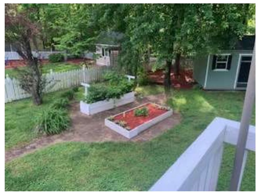 Antenna location in the backyard.
This picture shows where the antenna is mounted. As you can see it is not easily viewed at all. Even though I do not have any HOA or restriction issues. I think this antenna could be used in an environment where such concerns exist with great effect. The antenna is mounted on a fence post behind the tree shown just to the left of the tool shed. That tree provides the vertical support.
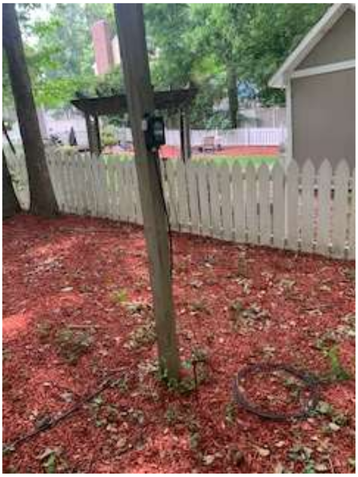
This fence post is behind the tree in picture one. You can see the ground rod at its base. The coax is buried along with the ground wire bonding that rod to the house. The wire goes up 80 feet supported by the tree before going horizontal.
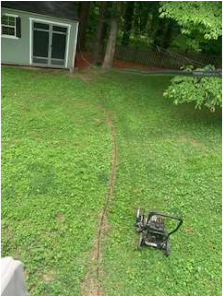
Here you can see the trench that AD4GX dug with the machine in the picture and the coax temporarily suspended above the ground before we put it into the trench. Within a week the grass had grown over the trench and there is no sign of it now. You can also see the 600 ohm feeders from one of my other antennas in the upper right of the picture. That is suspended at an elevation of 10 feet across the back yard.
Picture 5 – KM4JRH working on the waterproof junction box for the polyphaser and the coax switch that allows me to use the antenna on either the porch or in the radio shack.
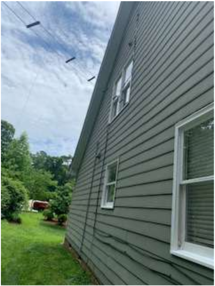
Picture 6 – The coax and electric cords mounted on the side of the house going into the radio shack. You can also see the open wire and ladder line feeders coming in.