…that costs less than $300, can be carried in one hand in a small duffle bag, is less than 3 feet long when taken down, can be installed and taken down in less than 10 minutes by one person, does not require guy ropes, can handle legal limit power, and offers more than 5 dB of gain.
John K4EB, Brantley K4CBW and I recently started a small contesting club we call the Pinecone Amateur Radio Club (N4BCJ). We enjoy operating together in contests and one of our favorite things to do is portable multi-multi operations. For instance, in the most recent Virginia QSO Party, we rented a cabin in the Old Dominion State and set up 2 Yaesu FTDX10’s and wire antennas. One station ran SSB and the other CW. We came in second in our category. Inspired by that, we did a similar thing from a cabin in North Carolina last Field Day. We have a lot of fun. When we were at the Dayton Hamvention this May we were captivated by the “portable” hex beam antenna systems and spent a good while drooling over them and thinking about how nice it would be to have a beam in our modest portable contest setups. But towers, guy wires, masts, all seemed like too much work and cost to me. But John and Brantley both remined me of how much FUN it would be. That got me to thinking about how to build a portable, inexpensive, easy to transport, install and take down, beam. Hmm.
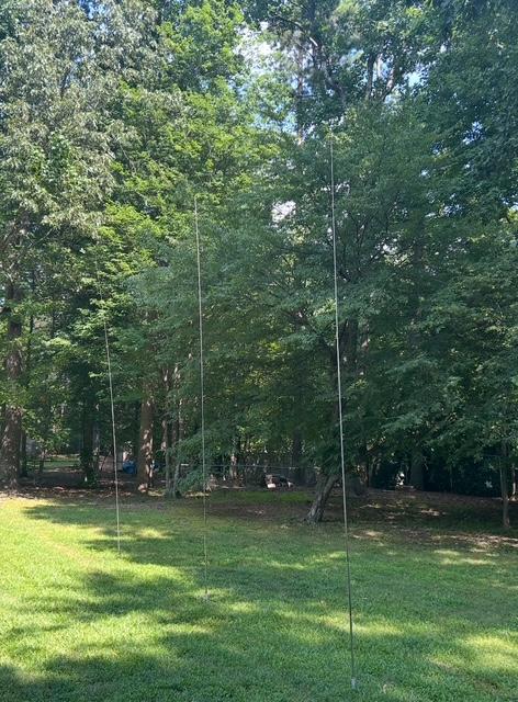
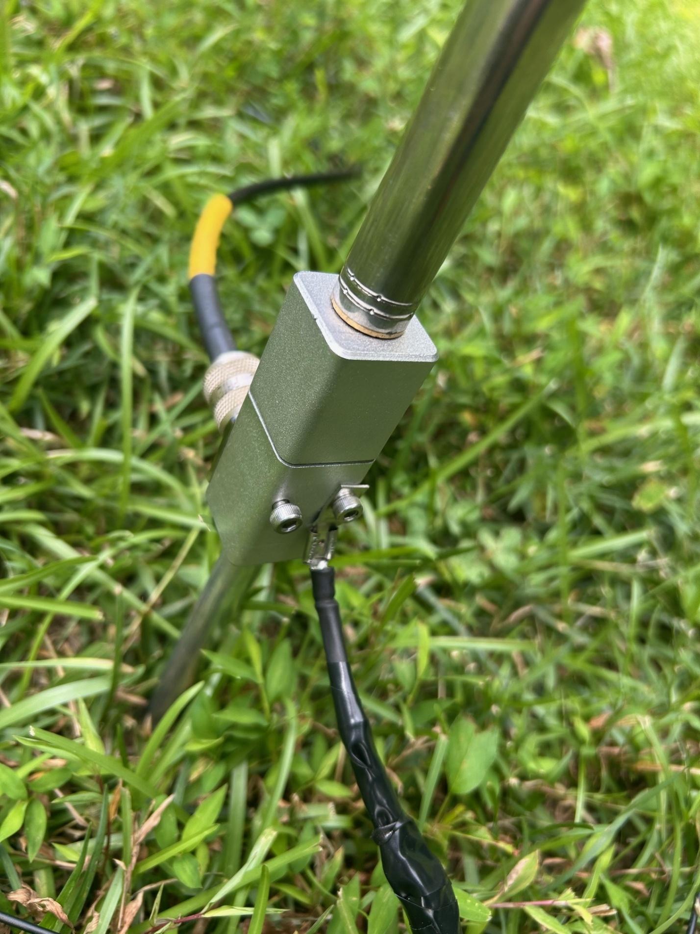
That evening we went out to do a Parks On The Air (POTA) activation and we used my favorite POTA antenna. I use a 17 foot long vertical telescopic whip that mounts into a tent stake style mount. The coax connects to the mount and so do 4 radials that slide onto the tent stake using a spade connector. I use this antenna frequently during my many POTA operations. It goes up and down in less than 5 minutes and requires no trees or ropes or guy lines. I got mine on e-bay and paid less than $50 for the entire antenna system. As I looked at that antenna I had the idea of adding a director and reflector to it and making it into a 3 element beam. That should work! I thought. Because I like this antenna so much, I bought several spares, that way if one breaks, I am not off the air. Having 3 of these antennas also allowed me to make a 3 element beam by using one for the Director, one for the Driven Element and one for the Reflector.
I had never seen another ham do this, but I knew the idea couldn’t be new, so a bit of internet searching was in order. I found a 1971 QST article by Jerry Sevick W2FMI entitled “The W2FMI 20-Meter Vertical Beam”. I highly suggest that you read that article, which can be viewed on the ARRL webpage in the Periodicals Archive section. In this article Jerry describes doing exactly what I had envisioned. He didn’t use telescopic whips, he used wires and built supports to hang them. However, electrically the antenna is the same as the one I envisioned. He measured 5.2 dB gain over a ¼ wave vertical with his 3 element beam. He also discovered he had to use a 4:1 transformer at the feed point to match the impedance as the parasitic elements impacted feed point impedance. Armed with that knowledge I set out to see what I could do.
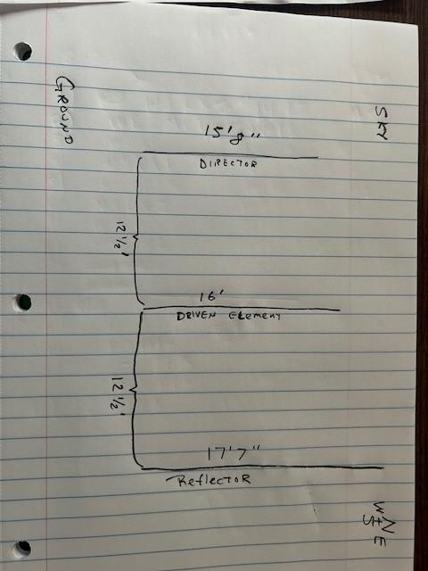
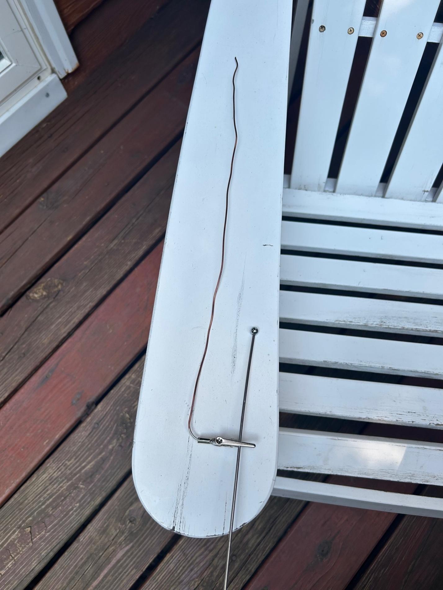
Following Jerry’s instructions, which are the simple math for yagi antenna element size and spacing, I made the Driven element 16 feet tall as I usually do. 12.5 feet to the West of that I placed the Director which I extended to 15 feet 8 inches. 12.5 feet East of the Driven Element I placed the Reflector which I extended to 17 feet 7 inches. The telescopic whip I was using is only 17 feet tall, so to get the extra 7 inches, I took a length of number 12 solid copper wire, soldered an alligator clip on one end, bent it at 90 degrees after the solder connection and alligator clipped that wire to the top of the telescopic whip at a location that would make the total antenna length 17 feet 7 inches.
I then measured SWR. I had 2:1 on 20 meters. I added the 4:1 transformer mentioned in the article and the SWR was worse. I went out to adjust the element length. Then I decided to try matching SWR without the transformer. By simply shortening the driven element length several inches I was able to match the impedance and get a 1:1 SWR without the need for a transformer in the feedline. Having a modern antenna analyzer made this task much easier than it was in 1971 for W2FMI.
The next test was to see how the radiation pattern looked. Fortunately, I have Reverse Beacon Network whereas W2FMI had to rely on making lots of contacts and getting signal reports back in 1971. I simply called CQ a few times on 20 meter CW and looked at RBN.
The difference the beam made was drastic.
Here is the antenna pattern with just the ¼ wave vertical antenna. As you can see, it is very omni directional.
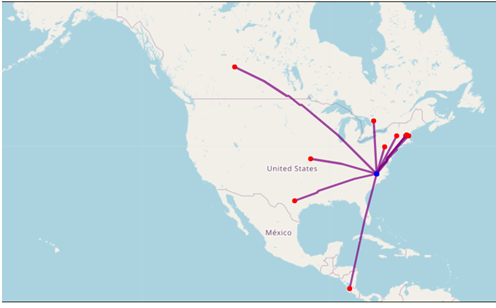
There are no RBN hits in the Atlantic ocean so East doesn’t show up much in this, but we can assume there is signal there, just no one to hear it. If we were to draw a line connecting the dots of each hit on this map it would make a circle shape (again allowing that there weren’t stations in the Atlantic). This is what I would expect from a quarter wave vertical antenna.
Now look at the RBN hits when we used the beam pointing West from Raleigh, NC:
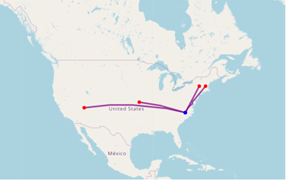
There were two hits off the side of the beam in New England, all the other hits were straight West of us. Stations in other directions that heard my signal before now did not hear it as they were not in the beam’s path.
What does this show? Well, it shows you can make a relatively inexpensive, very portable, easy to put up, take down, and transport beam antenna that works fairly well at being a beam!
If you are going to build this and use it many times, here are a few hints:
- Get several colors of kite string. Use a different color string for each of the following items. a. Cut two lengths of kite string to 12 feet 6 inches. Label them with masking tape “Element Spacing”. b. Cut one length of kite string 17’7” and label it with masking tape “Reflector” and put an alligator clip on one end. c. Cut one length of kite string 16 feet and label it with masking tape “Driven Element” and put an alligator clip on one end d. Cut one length of kite string 15’6” and label it with masking tape “Director” and put an alligator clip on it.
Now when you go to the field to install this antenna. Use the 12 and a half foot strings you cut in item A to measure out the spacing between the elements. I suggest tying the string around the base of each element. That way if you want to “Rotate” the beam, you leave the driven element in place, move the director on that string, keeping the 12.5 feet spacing, then move the reflector on its string, keeping the 12.5 feet spacing until it is in the same plane as the director. Doing that will rotate the beam’s direction while keeping the spacing.
When you go to push up the elements, alligator clip the correctly labeled string to the top of your antenna, and slide the antenna up until your string shows you have it at the correct length. This will prevent you having to measure each element with a tape measure each time. Keep these strings from getting tangled by storing them on a wire winder.
If you have an antenna analyzer you can use that to make final adjustments to the length of your driven element for lowest SWR. Or, you can use your radio’s built in SWR meter, or just use the radio’s built in antenna tuner to match the system if your radio has one. Or use an external tuner if needed.
This will get you a beam on the air quickly. With any vertical antenna, you will need good ground radials if you are in an area without good soil conductivity. The more the better.
Of course, you don’t always WANT a beam. When I am activating a park for POTA, I want to make as many contacts as possible in all directions, so I like the way a vertical antenna’s omni directional pattern works. However, if we are in a contest and trying to work a specific part of the country, a beam is nice. Also, it can keep RF away from another antenna, thus reducing inter-station RFI in a multi-multi setting. So beams have their place, but so do less directional antennas. It is all about using the right tool for the job and it is nice to know that it is “easy” to get a tool that is a 3 element beam that doesn’t break the bank, can be transported easily, installed and taken down quickly, and be a fun way to play radio in a park or other portable setting (or even at your home).
Schematic Drawing of Antenna:
How I added length to the Reflector:
How the Radials Connect:
eBay Links to the antennas and parts used:
- Antenna Carry Bag: $21 https://www.ebay.com/itm/285603579968
- Tent stake ground mount SO-239 to M-10 $38.00 https://www.ebay.com/itm/146597144123
- Telescopic Vertical Antenna : $20 https://www.ebay.com/itm/226768708847
- Ground Radial Kit: $40 (or make your own) https://www.amazon.com/dp/B076DLVJ1L?ref=nb_sb_ss_w_as-reorder_k3_1_13